After setting up my Surface Pro with Windows 10 and IoT core I decided that in order to demo it all I needed a Windows 10 VM with it all on. I had a couple of issues that I didn’t get on my Surface Pro.
The first issue I had was that the Windows IoT core watcher application would not run properly and kept shutting down. This is a known bug and has a work around:
Launch the "Developer Command Prompt for VS2015" as Administrator
change the working directory over to "C:\Program Files (x86)\Microsoft IoT"
sn -Vr WindowsIoTCoreWatcher.exe
corflags WindowsIoTCoreWatcher.exe /32BIT+ /FORCE
The second issue was Visual Studio couldn’t connect to TFS online. When I tried to manage connections I got the following error:
SplitterDistance must be between Panel1MinSize and Width - Panel2MinSize.
This seems to happen on both VS 2015 Enterprise RC and Community RC editions. I found a work around as follows:
Open up Team Foundation Server online at <youraccount>.visualstudio.com. Click code, then navigate to the project you want to open, click on the solution file which then opens the solution in the web editor. Click the visual studio icon and VS opens with the team project now in team explorer. Close VS and open it again and your team project should still be connected to team explorer
Now with Visual Studio working I needed to set Windows into developer mode. This can be done as follows:
Start->settings->Update & Security -> For Developers. However, when I tried this the setting page kept closing. You can also use the Group Policy editor (Gpedit.msc) as follows:
https://msdn.microsoft.com/en-us/library/windows/apps/dn706236.aspx

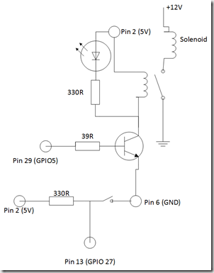
In my previous Raspberry Pi Post I talked about using the Raspberry Pi to turn an LED on an off. Now whilst this is pretty, its not really that useful. So I wanted to use the same program but to turn on something that needed a bit more power than an LED. I’d recently acquired a solenoid (a coil with a bolt that gets draw towards the magnetised coil when 12v is applied to the solenoid’s coil). Now my Pi doesn’t have enough power on its own to drive the solenoid so I needed a mechanism to apply 12v to the coil from a 3.3V output that the PI delivers. This meant I had to think back to my school days, which in my case is a difficult task :-). I remembered that I could use a transistor to turn on something with a bigger current from a smaller one. I decided that as the Pi can supply both 3.3V and 5V I would use a 5V relay and a transistor to allow me to turn on a separate 12v supply to the solenoid. I tried to calculate the correct resistors for the circuit but I failed miserably so in the end I decided trial and error was my best plan. I used a NPN transistor and a resistor and I also combined the LED and resistor from the previous post. The other change that I wanted to do was to remove the timer, that was being used to turn the LED on and off, and replace it with a push button switch.
The following shows the circuit I used.

I should really use a diode across the resistor to protect the transistor and I’ve even used my soldering iron without burning my fingers.
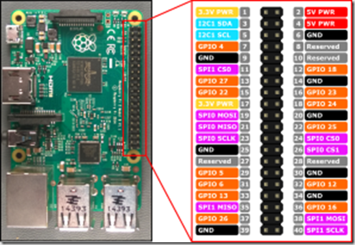
For information, the following image shows the assignment of pins for the Raspberry Pi 2:

Anyway, In order to change the code to use a push button I took the sample https://www.hackster.io/windowsiot/push-button-sample and added the push button code to my blinky sample and removed the timer turning on the LED.
In order to use the push button I needed to configure one of the GPIO pins for input rather than output that was used for turning on the LED. I still needed to use a timer, as I needed to read the push button pin on a regular basis to see when the input changed to low when the button was pressed.I set the time to 250 ms so that I didn’t have to hold the button down too long for it to register, but not too long that the timer would hog all the resources on the PI.
Now when I press the button the LED turns on, the relay clicks and the solenoid pulls the bolt across. It made me jump when I first connected it up as the solenoid made quite a loud bang and I though I’d blown something up!!
I think I know enough now of how to use the GPIO on the Raspberry PI so I am looking at how I can now connect the PI up to Azure and make it part of a distributed system.
More on this to come……